What is an OTDR?
An Optical Time-Domain Reflectometer (OTDR) is a device that uses light pulses to measure the properties of an optical fiber. It sends light pulses into one end of the fiber and detects the light that is backscattered along the fiber. It then calculates the intensity and timing of the returned light and displays it as a graph of fiber length versus signal strength.
An OTDR can be used to find out the length and attenuation of a fiber, as well as the losses caused by splices and connectors. It can also identify faults, such as breaks, and measure how much light is reflected back by the fiber. To get more accurate results for multiple fibers, it is better to test from both ends and take the average, but this takes considerably more time and effort than testing from one end only.
An OTDR is a complex device that combines special optics, electronics, computing and display functions. It can automate some of the testing processes, but it still needs a skilled and trained operator to use it correctly and interpret the data.
How does an OTDR work?
OTDRs work by sending a short pulse of light into the fiber and then measuring the amount of light that is scattered back to the OTDR. The amount of backscattered light is proportional to the loss of the fiber, so by measuring the backscattered light, the OTDR can determine the loss of the fiber at any point along its length.
Rayleigh scattering is a phenomenon that occurs when light travels through a material. The light waves are scattered by the molecules of the material, and this scattering is what causes the light to become diffused. In an optical fiber, Rayleigh scattering is the main cause of loss.
As the light is scattered in all directions when travelling through a material, some of the light will return back along the fiber towards the light source, where OTDR will takes measurement of this portion of the light. The backscattered power is proportional to the incoming power. The returned power also gradually diminishes as the losses take effect on the incoming power. Moreover, wavelength is proportional to the signal of pulse width, the power of Rayleigh scattering is directly related to the wavelength of emission signal. In another word, the shorter the wavelength, the stronger the power.
An OTDR measures the properties of a fiber by using the light that is naturally scattered back to its port. It emits a very strong pulse of light and continuously detects the light that returns and deduces the losses throughout the fiber.
It can detect the changes in the returned power level and measure the losses in the fiber. Any sudden losses, such as connectors and splices, cause a drop in the transmitted power and a corresponding change in the scattered power.
An OTDR can locate and measure these losses by timing and analyzing the returned light. The OTDR can also see reflections from connectors, splices or the end of the fiber, which appear as spikes above the trace. These reflections can be used to mark distances or calculate the back reflection, which is an important parameter for single mode systems.
An OTDR can relate the scattered light to the position in the fiber by calibrating the speed of the pulse. The OTDR can then display the amount of scattered light at any point in the fiber. The power loss is a logarithmic function, so the power is measured in dB.
The amount of light scattered back to the OTDR depends on the backscatter of the fiber, peak power of the OTDR pulse and length of the pulse. If you need more scattered light to get better measurements, you can increase the peak power or length of the pulse.
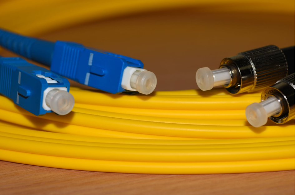
An OTDR usually needs a launch cable and may use a receive cable for testing. The launch cable gives the OTDR time to recover after sending out the pulse and provides a reference connector for measuring the loss of the first connector on the cable under test. A receive cable may be used on the other end to measure the loss of the last connector on the cable under test as well. Therefore, it is recommended to always keep two reference cables in the OTDR set.
Key measurement parameters
There are four typical parameters to be set on an OTDR,
- Wavelength – Traces at longer wavelength are more sensitive to stress.
- Range – The range should be set to at least two times the length of the cable in order to prevent trace distortion and ghosting.
- Pulse width – Minimizing the pulse width will ensure better resolution but more noise and shorter range. While bigger pulse width means more energy, hence longer detection range and less noise, but the tradeoff is less distinguishable events.
- Number of averages – In general, more averages will lead to reduced noise and improved visible details. In another word, more averages will yield better traces but will take longer.
Common problem with OTDR measurement
- Ghosts
Ghosts are likely to happen when short cables with highly reflective connectors are under test. These phenomena are caused by the reflected light from the far end connector reflecting back and forth in the fiber until it is attenuated to the noise level.
Ghosts are confusing as they are very similar to real reflective events like connectors, except they do not show any loss. When a reflective event in the trace happens at a point where there is no actual connection, and the connection from the launch cable to the cable under test is highly reflective. Make sure to look for ghosts at multiples of the length of the launch cable or the first cable under test.
- Splice & connector loss errors
This problem mainly arises when there is a difference in back scattered light at a splice point. The back scattered light is a function of attenuation of the fiber and the diameter of the core of the fiber. Fibers with higher attenuation results in more attenuation because more light is being scattered.
If both fibers at a splice point are identical, the backscattering will be the same on both sides of the joint, so the OTDR will take measurement of the actual splice loss with no error.
If fibers on both sides of the splice point have different attenuation, the measured loss on the OTDR will include the actual loss plus a loss error caused by lower backscatter level when light travels from a fiber with higher attenuation to fiber with lower attenuation or yield a gainer when the light travels in the opposite direction.
- Dead zone
The term dead zone arises from an event with strong optical reflection reaches the OTDR, the detection circuit is saturated during a certain period of time and is incapable of recovering to measure backscatter accurately. This phenomenon results in the OTDR not properly displaying the reflection of a part of the fiber link after this event. There are two typical types of dead zones:
- Event dead zone: this type of dead zone refers to the minimum range needed for consecutive reflection events to be distinguished from each other.
- Attenuation dead zone: this type of dead zone refers to the minimum range required after a reflective event, in order for the OTDR to measure a loss of reflective event or a reflection.

